
Heavy Brush 3 and Heavy Brush 4 - detail for Firefighters
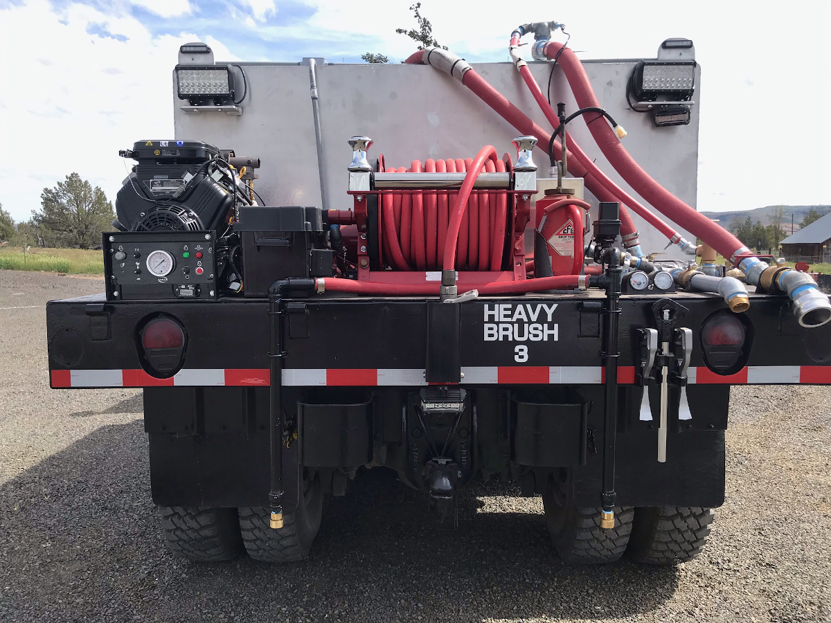
The following four pictures provide more information about the layout of equipment on the trucks. Note that the trucks are designed primarily for initial attack (running attacks), but also can be used as stationary supplies for a blitz attack or progressive lays through the 4 number 3 valves and ports.
This rear view shows the layout of the pump (left), the
quick-connect fill port (extreme right), the hose reel (center),
drip torch (mounted adjacent to the hose reel, the #3 port and valve
(just left of the fill port) and the two rear bumper nozzles
(directed down, appearing in front of the inboard tires). The
black box between the pump and the hose reel houses the battery for
starting the pump.
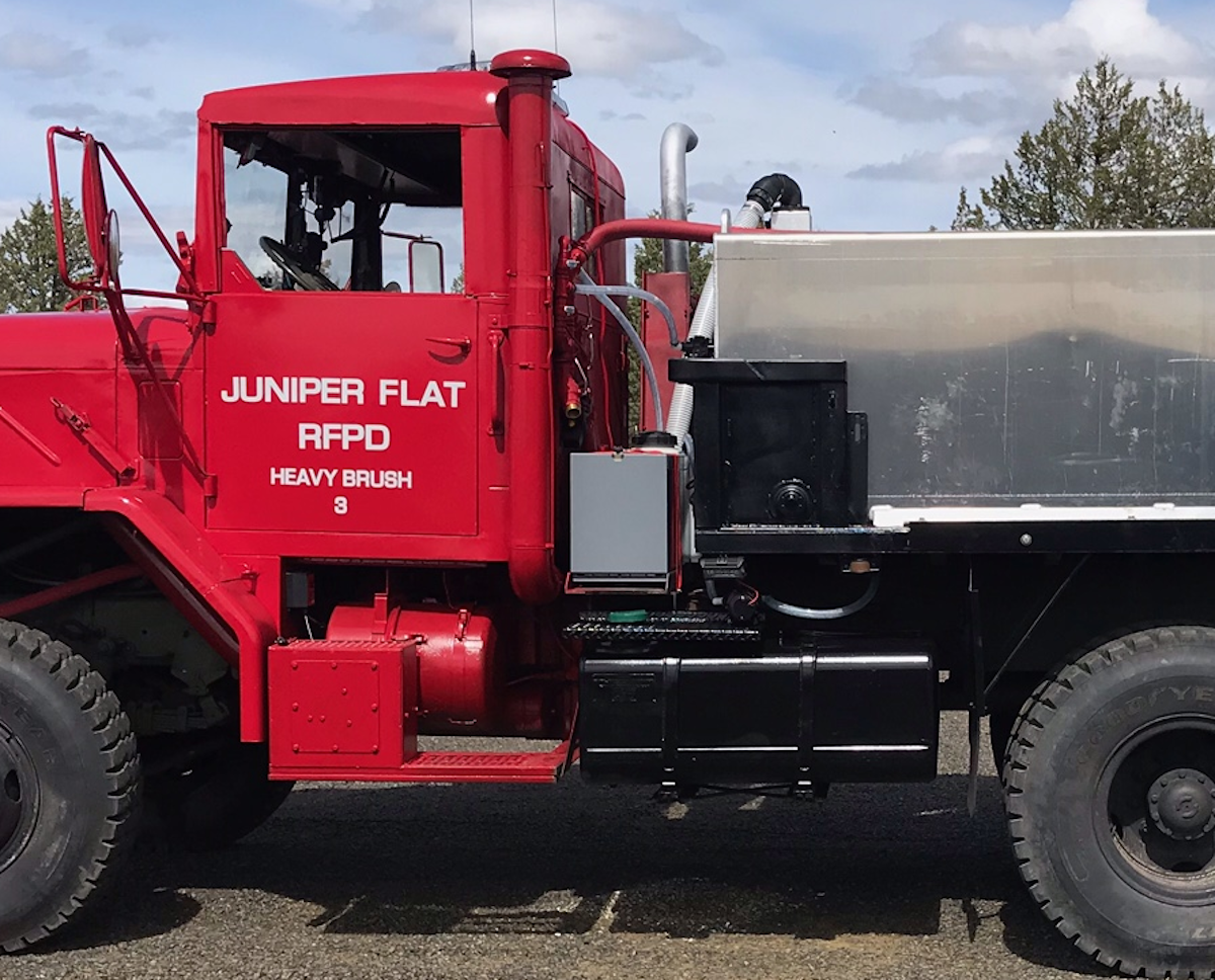
Detail of the driver side of the truck. The gray box contains preconnected blitz attack hose (200' at present); a number three valve and port for stationary attacks are above and to the left of the box on the rear of the cab. The foam tank (white with black lid) is just visible behind the gray box; the large, white, semi-rigid hose behind the box and connected to the tank tower (with a black elbow) is the tank overflow. Smaller clear hoses connect electric pumps to the foam system - valves are located on the manifold mounted to the rear of the cab.
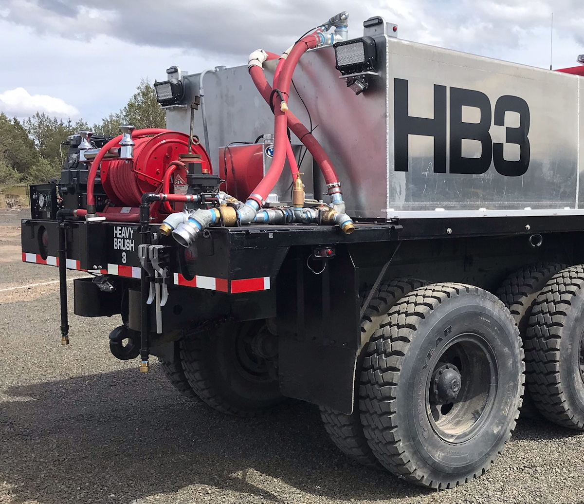
Detail of the rear, left quarter shows one of the three #3 valves and ports (forward and to the left of the pump in this image) as well as the left rear scene light mounted high on the tank:
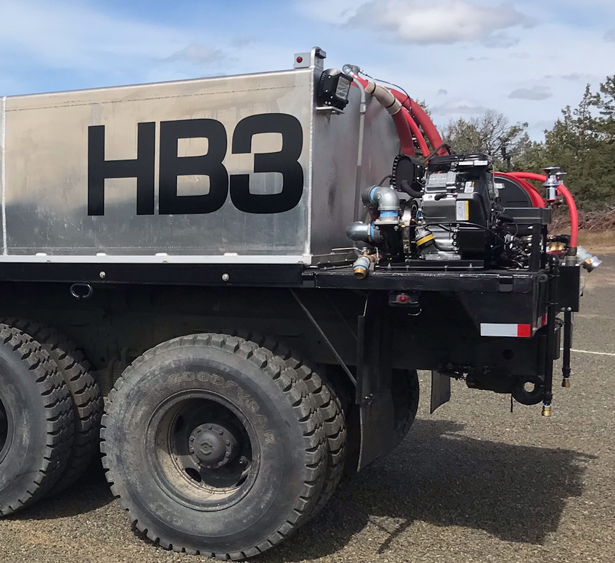
Detail of the right rear quarter shows the other two #3 valves and ports on the back of the truck and the right rear scene light. The smaller light below the scene light illuminates the water supply manifold and work area on the trucks rear platform. The smaller rectangular aluminum tank behind the red hoses is the gas tank for the pump.
Water Usage
When using bumper nozzles and the monitor be mindful of the rate that water is used. Though large, the tanks have a limited (1650 gallon) water supply. The monitor has a 1/2" smooth bore nozzle, so uses water at the rate of about 60 gallons/minute (gpm) at an engine pressure of 100 psi and 90 gpm @ 150 psi (not taking friction loss into account). Nominally, you have anywhere from 18-27 minutes of supply when using just the monitor. We are trying to set the bumper nozzles at 30 gpm at an engine pressure of 150 psi (probably the water usage will be around 55 gpm when two nozzles are in use simultaneously). So, in theory, you have about 55 minutes of supply for a single bumper nozzle and 30 minutes when running two nozzles. Of course, no one ever uses the monitor or bumper nozzles in isolation, so the actual supply will be a more complicated function of the combination of nozzles and monitor in use. One piece of data that helps to inform your estimate of supply is the rate that the pump can supply water to the entire system (as a function of engine pressure). The following graph from the manufacturer (IDEX/Hale) provides those data:
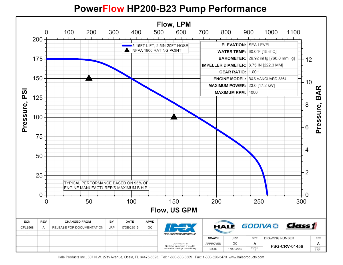
Note that at our nominal engine pressure (150 psi), the pump is rated to deliver about 100 gpm. As more nozzles/monitor are turned on, the pressure will drop.